Q&A With HELU: Cable Assemblies

Not all cables are hard-wired when they are terminated in their intended application. Some are terminated with something as simple as a ferrule or lug, while others are more complex and use a combination of male or female pins that are inserted into standard or custom connector housings. Cable assemblies can be built either by third-party assembly houses or directly by the cable manufacturer to streamline the supply chain and provide better value to the end user. Keith Wilkerson, HELUKABEL USA’s Business Segment Manager – Robotics & Automation, answers questions he hears in the field about when a pre-assembled cable makes sense, and what to think about when you choose to pre-assemble a cable.
Q: When would a machine builder or end user want to use a cable assembly over hardwiring?
A: Thanks to low installation costs, hardwiring remains the most common way to bring power and data signals to a machine. However, it is important for all parties involved in the design/build process to consider the total cost of each option. Hidden installation costs associated with hardwiring have their own labor and time-to-market considerations. For example, many machines must be disassembled for shipping and reassembled on site, meaning the machine must be hardwired twice. In addition, field wiring errors can cause commissioning delays or can even damage a machine. Subsequent on-site testing of the hard-wired systems can be complex and expensive. After installation, reducing downtime for scheduled maintenance or caused by unforeseen disruptions is crucial. When disruptions occur, not if, replacing hard-wired cable can take hours. Cable assemblies enable “plug-and-play” installation of modular machine sub-assemblies (systems), which saves time and ensures wiring integrity. When you factor in wiring costs, including initial wiring at the machine builder, routine maintenance, and repairs requiring certified electricians and all other sources of downtime those initial savings seen with hardwiring can quickly evaporate. The advantages of “plug-and-play” solutions aid in making machine systems easier to ship, assemble and maintain, while also being more cost-effective over the long term.

Q: What are a few of the biggest challenges in designing a “plug-and-play” assembly for a new project?
A: Like with any system, ensuring all the individual components will work together as one final, cohesive product is the name of the game. For instance, if a connector utilizes crimp and poke technology it is important to confirm the individual cable conductors not only match the wire gauge, or the circular mil area (CMA), but the insulation crimp must also be taken into consideration. The same can be said for the diameter of the outer jacket. Whatever method of strain relief is used should match the cable and connector. Otherwise, the strain relief may be too tight causing undue stress on the cable itself or if it is too loose it will contribute to possible downtime due to open circuits. Matching the connector to the ampacity and voltage requirements is also of great importance. Finally, especially in the case of RJ45s and other Fieldbus systems, selecting a connector that is designed for the type of conductor, solid or stranded, can impact data rates and lost packets if not specified properly.
Q: Are cable assembly pinouts standardized or can they be customizable?
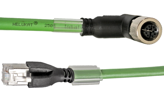
A: The answer is yes to both points. With standard automation cordsets, such as M12 A-coded and Industrial Ethernet assemblies, pinouts are the same across all manufacturers. Even though these types of cordsets are produced to a standard, end users should be cautious and consider the overall application. For instance, a manufacturer could offer a few different part numbers in a particular configuration. The difference is most often the cable specifications. If the cordset is going to be utilized on a robot arm (axis 3 to axis 6) a PVC-jacketed cable with a “static” or “stationary” rating would be doomed to fail.
Application-specific designs that do not follow an industry standard require a more detailed level of engineering and component-level product knowledge. There are many choices in the world of connectors and cables. Environmental considerations, electrical requirements, third-party norms, and many other parameters influence and can impact the overall success of a custom-designed harness. A good supplier base with the technical resources to assist an end user is needed when designing a new harness from a blank page.
Q: Which is a better strain relief solution, mechanical backshells or overmolded?
A: They each have their pros and cons. Mechanical backshells consist of a housing that is screwed on or affixed in some other manner such as a two-piece clamshell or a collet. These are normally assembled by hand and are more labor-intensive. Therefore, overall labor costs may be higher. Mechanical backshells are ideal for low-volume production runs. This is advantageous if you’re needing a faster development time. The purpose of overmolding is to create the best possible adhesion between the cable, connector and the overmold material. Overmolding improves the overall performance of the assembly. The most notable advantage of overmolded cable assemblies is that they lend themselves to higher volume production runs due to the efficiencies of the manufacturing process. The most common pushback related to overmolded assemblies is repairability. The question then becomes, “What needs to be repaired?” Broken terminations or pushed pins are the most common problem. Other problems may be fractured wire terminations, in the case of solder joints, because of the cable pulling away from the connector insert. These common failures are all but eliminated with an overmolded solution.
Q: What are the steps in producing an overmolded cable assembly?
A: We will briefly cover the basics. The process begins the same as building any cable assembly by cutting the cable to length and preparing it for termination. Individual conductors are soldered or crimped per the manufacturer’s instructions. At this point, testing for shorts and opens should be conducted because once the pre-mold step is completed any repairs or rework cannot be performed and the assembly must be scrapped. The next step is the pre-mold. This step in the process allows for full encapsulation of the individual conductors and the cable jacket. This provides a robust mechanical bond between the cable and the connector. The final step is the overmold. This is what gives overmolded assemblies their clean, high-value look. The “fins” at the back end of the mold provide strain relief for the cable itself.
Q: What other considerations should be considered when an overmolded assembly is selected?
A: The outer diameter of the cable needs to be known in the design phase. Depending on the mold tool, adjustments may be required to accommodate a smaller or larger cable. That may lead to a simple modification of the mold tool or some machining time. Most often machining time will be covered by a non-recurring engineering (NRE) charge. Connector size is a limiting factor as well. Most mold machines can only accept up to a size 32 shell, an M40, or about 70 mm in diameter. The base material for an overmold is also important. Most often the best solution is to use the same material in the overmold as the cable jacket. So, if the cable jacket is polyurethane (PUR), then the overmold material should be PUR. This will allow the proper bonding of the materials to one another if molded correctly. The same rule holds for PVC and TPE jacket types.

ARTICLE DOWNLOAD
Click here to view this article in our digital download centre.
